Tutorial 1, Part 5 – Hatch the Road
Pick here to see an online movie of Tutorial 1 Part 5
To make the pavement area look correct, we can hatch it. This is an optional step and is not necessary for a normal diagram printout.
Hatching
The Draw Lines Command
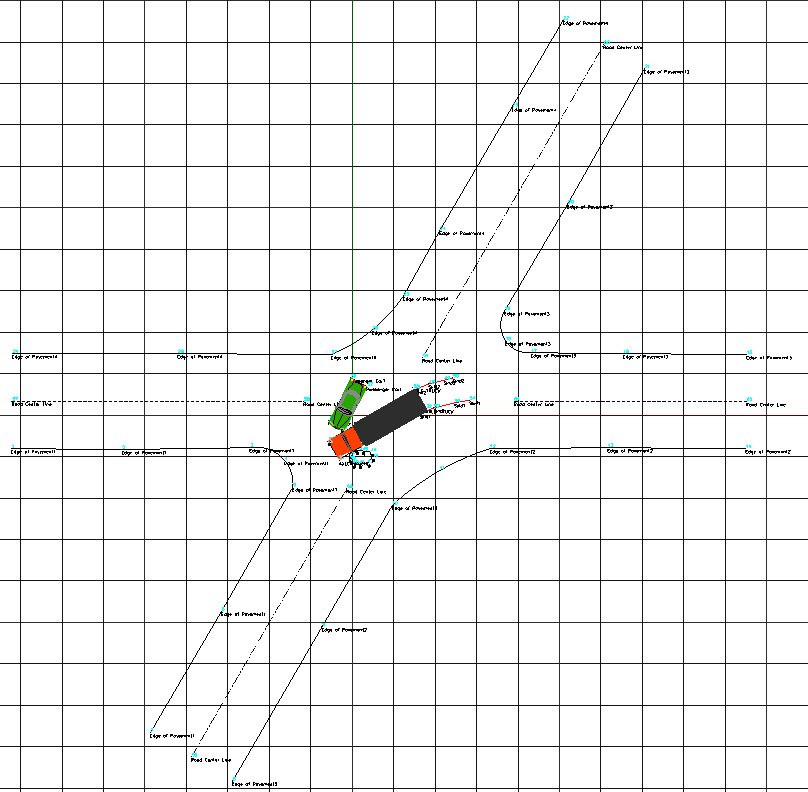
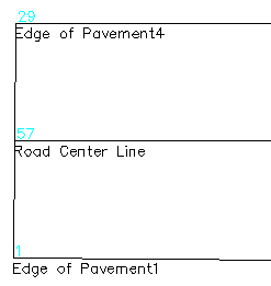
To be able to shade in the road area only – we need to draw 4 short lines at the ends of the 4 arms of the road. This will cap them off so we can shade them in.
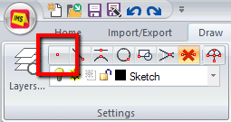
- Switch to your "Draw" ribbon and select the endpoint snap from the "Settings" group shown above.
-
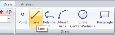
- Select "Line" from the Draw group:
-
- Place the mouse over the end of the line and left click when the red square (snap icon) indicates that the endpoint has been selected:.
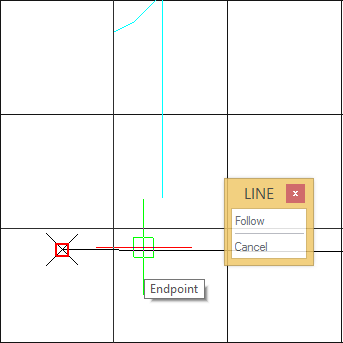
- Move to the end of the second line and pick when you see the or snap icon.
- Right click to finish the operation, or hit the "esc" key to start again.
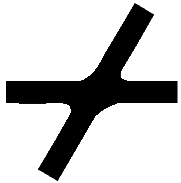
- You will see a line drawn like this.
- Do this on all 4 arms of the road.
Handy hint:
If you right click you will see the option to repeat the last command.
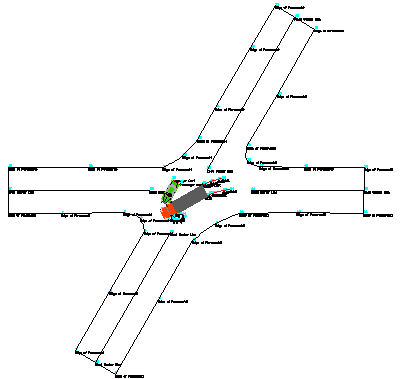
The Result:
Drawing a Boundary Hatch
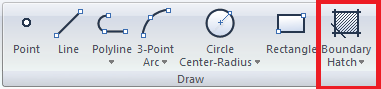
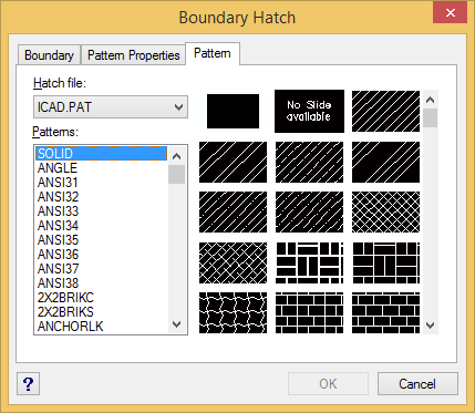
Pick "Boundary Hatch" from the Draw group, Pick the Pattern tab, and select the SOLID pattern name.
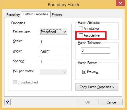
Click the Pattern Properties tab and turn off the Associative option.
This will allow us to erase the 4 lines we drew to cap off the arms of the road, if we wish to, without affecting the hatch of the road.
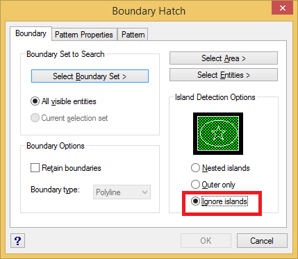
Click the Boundary tab and select the Ignore Islands option.
This will allow us to hatch the entire roadway without worrying about the text or symbols we have inside the roadway.
Click the "Select Boundary Set" button.
Defining the Boundary
The Boundary Hatch dialog will temporarily disappear. On the Status bar in the lower left corner you will see: "Select Entities." Left click all the lines that define the edge of the road. Note how they will appear as "dashed" once you have selected them. Right click once you have defined a closed area:
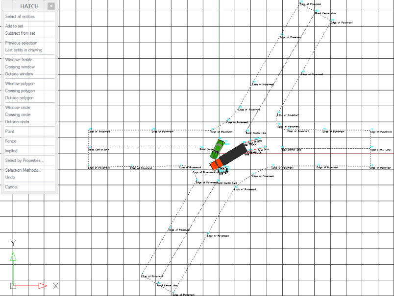
The Boundary Hatch dialog box will then reappear.
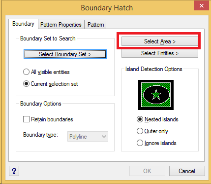
Click the Select Area> button.
The Boundary Hatch dialog will temporarily disappear. On the Status bar in the lower left corner you will see: "Specify Internal Point." Left click anywhere inside the intersection. A preview will appear so you can confirm that the area is correct. Right click if it is correct, or hit the "esc" key if you wish to start again. The Boundary Hatch dialog box will then reappear.
Click OK to continue.
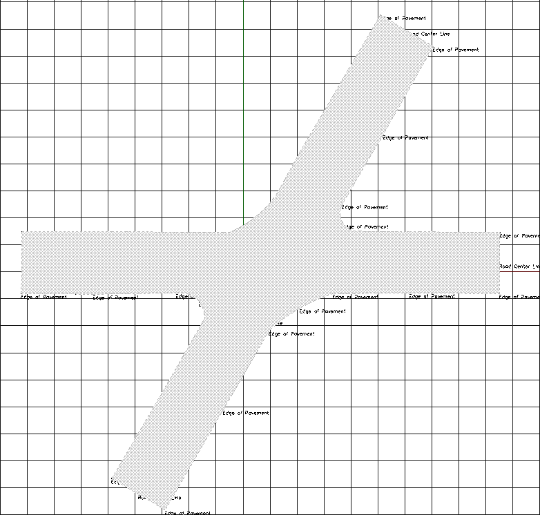
The road area will now be hatched in solid black.
Modifying the Hatch Properties
Next we need to change the color of the road to a gray color. Select the hatching by either:
- picking inside the hatched area
- drawing a right to left selection window over the edge of the hatched area
- or Left clicking on the edge of the hatched area, Right clicking and selecting "Properties."
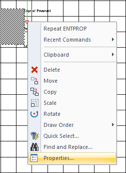
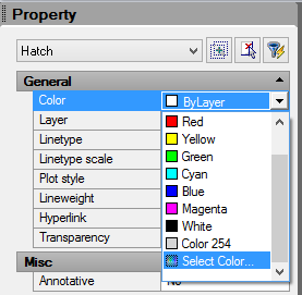
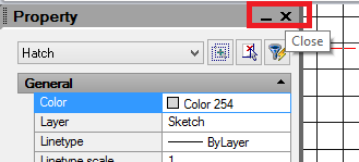
The Entity Properties palette will appear on the left side of the screen. From the "General" properties category pick the pull down next to "Color" and pick "Select Color:"
Pick the desired pavement color, for example the last grey on the second line.
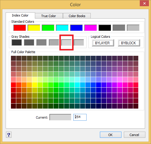
Click OK to close the Color dialog. And Pick the "X" in the top right corner of the palette if you wish to hide the Properties:
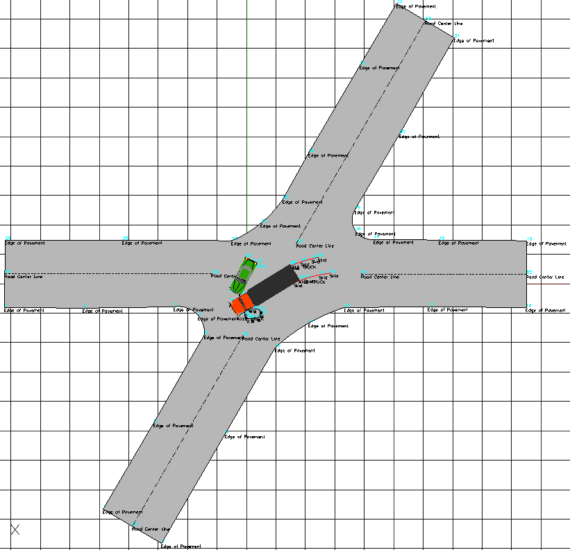
Now you will see the pavement hatching in the color you choose:
Draworder
The road hatching may now appear to cover everything else on screen. To solve this we can change the . The Road hatching needs to be placed under everything else so we can see the whole scene.
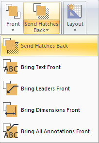
Select your hatching by picking the edge of the hatched area. The switch to the "Draw" Ribbon and select "Send Hatches Back" from the "Draworder" Group:
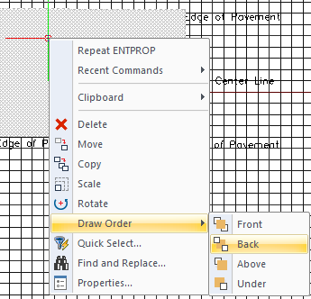
Alternatively, we can achieve this by left clicking on the edge of the hatched area and right clicking and selecting "Draw Order," then ""Back:"
Now the road hatching will sit under everything else on screen:
Save
Pick the "Save" button to save your work: