Tutorial 1, Part 3a – Manual Baseline/Offset Entry
(If you used Evidence Recorder SyncWizard to import the field data, skip ahead to Part 4)
(If you wish to read in an ASCII file instead of manually typing all of these measurements in, skip ahead to Part 3b)
The Baseline Offset method allows you to use IMS Map360 when you do not have a total station, GNSS sensor or scanner for collecting evidence. Experienced users have been able to create effective maps using simple measurement tools for decades, and IMS Map360 continues to support this method.
Switching the Workspace
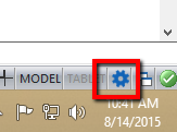
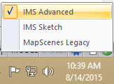
To perform Baseline Offset entry, we will need to switch to the "IMS Advanced" workspace by picking the gear icon in the bottom right corner of the screen:
Hot Toggles
Then switch to the "MsTools" ribbon and Pick "Hot Toggles" in the "Defaults" group:
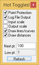
This will allow us to auto-number starting at 100 for the baseline we will be creating.
Starting the Baseline/Offset Editor
Now switch to the "MsMeasurement" ribbon and pick from the "Input" group:

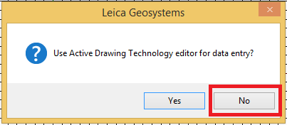
Click No to enter in the baseline/offset measurements on the command line. We will use the command line in this example to enter the data. Answer each question by typing in the correct data, then pressing enter.
Do you want to start a NEW baseline, or continue adding points from an EXISTING baseline?
Enter N or E : N
Which direction do you want the baseline to run?
Enter N or S for NORTH/SOUTH, OR enter E or W for EAST/WEST : E
Is the starting end of the baseline at the EAST END or the WEST END?
Enter E or W : W
What are the coordinates of the start of the baseline? <1000.000000,1000.000000> -100,0
Enter the distance along the baseline : 200
You must define a positive offset as being to the LEFT or RIGHT.
Enter L for LEFT OR R for RIGHT : R
You will then be asked for 4 pieces of information for every point to be recorded. The prompts will look like this:
Enter the distance along the baseline :
Enter the Offset:
Enter Description <>:
Enter Calculated Point number <>:
Completing the Input
Using the data supplied below, enter in each shot, 1 at a time.
| Distance | Offset | Description |
Point |
| -2.73 | 10.09 | EP1 ST | 1 |
| 30.60 | 10.37 | EP1 | 2 |
| 69.16 | 9.82 | EP1 STCV | 3 |
| 79.62 | 13.67 | EP1 | 4 |
| 82.10 | 21.66 | EP1 EC | 5 |
| 60.62 | 59.12 | EP1 | 6 |
| 39.14 | 95.75 | EP1 | 7 |
| 63.92 | 110.34 | EP2 ST | 8 |
| 90.91 | 63.80 | EP2 | 9 |
| 112.12 | 27.17 | EP2 STCV | 10 |
| 126.44 | 16.70 | EP2 | 11 |
| 141.59 | 10.09 | EP2 EC | 12 |
| 177.12 | 9.82 | EP2 | 13 |
| 218.70 | 10.09 | EP2 | 14 |
| 218.98 | -18.27 | EP3 ST | 15 |
| 181.80 | -18.55 | EP3 | 16 |
| 153.98 | -18.82 | EP3 STCV | 17 |
| 146.27 | -22.41 | EP3 | 18 |
| 145.99 | -31.49 | EP3 EC | 19 |
| 165.00 | -63.72 | EP3 | 20 |
| 188.13 | -104.48 | EP3 | 21 |
| 163.62 | -119.07 | EP4 ST | 22 |
| 148.20 | -92.91 | EP4 | 23 |
| 126.44 | -55.73 | EP4 | 24 |
| 115.42 | -35.90 | EP4 STCV | 25 |
| 106.06 | -25.71 | EP4 | 26 |
| 93.67 | -18.27 | EP4 EC | 27 |
| 47.40 | -18.55 | EP4 | 28 |
| -2.45 | -18.55 | EP4 | 29 |
| 92.64 | 8.01 | TRK_AXL | 30 |
| 96.09 | 13.72 | TRK_AXL | 31 |
| 122.22 | -1.95 | TRK_AXL | 32 |
| 118.28 | -8.26 | TRK_AXL | 33 |
| 96.88 | 4.45 | VEH1 | 34 |
| 92.89 | 1.66 | VEH1 | 35 |
| 99.46 | -11.24 | VEH1 | 36 |
| 104.41 | -8.64 | VEH1 | 37 |
| 99.25 | 11.75 | W ST | 38 |
| 99.25 | 13.53 | W | 39 |
| 100.14 | 14.71 | W | 40 |
| 102.01 | 14.81 | W | 41 |
| 104.67 | 14.41 | W | 42 |
| 105.95 | 12.84 | W | 43 |
| 105.56 | 11.16 | W | 44 |
| 103.00 | 10.77 | W | 45 |
| 101.22 | 10.57 | W CLS | 46 |
| 118.83 | -7.71 | SKID2 ST | 47 |
| 123.08 | -9.37 | SKID2 | 48 |
| 127.69 | -10.57 | SKID2 | 49 |
| 130.37 | -11.21 | SKID2 | 50 |
| 120.21 | -0.42 | SKID1 ST | 51 |
| 124.64 | -2.17 | SKID1 | 52 |
| 130.83 | -3.74 | SKID1 | 53 |
| 135.35 | -4.48 | SKID1 | 54 |
| 51.53 | 103.04 | CL ST | 55 |
| 98.35 | 22.16 | CL | 56 |
| -2.59 | -4.23 | CL ST | 57 |
| 85.40 | -4.17 | CL | 58 |
| 121.20 | -17.32 | CL ST | 59 |
| 175.88 | -111.78 | CL | 60 |
| 148.81 | -4.13 | CL ST | 61 |
| 218.84 | -4.09 | CL | 62 |
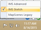
Restoring the Sketch Workspace
Now switch back to the "Sketch" workspace by picking the gear icon in the bottom right corner of the screen:
(When you have entered in all of the shots, you can skip to Part 3c to draw the code-based linework. In Part 3b, the same coordinates are read from an ASCII file of text that is supplied with the program. Either method will generate the same diagram in Part 3c.)
Save
Pick the "Save" button to save your work: