Tutorial 3, Part 1 – Start a New Scene
Before you begin, save yourself some time later by downloading the sample data. Files for this exercise can be downloaded from the link below:
Save this file to your computer, right click and "extract all..." This is a large file so allow time for it to download.
Pick here to view an online movie with an overview on creating a new drawing
Start the program using the IMS Map360 shortcut on your Desktop, or from the Windows' Start menu. When the program opens you will see the following dialog:
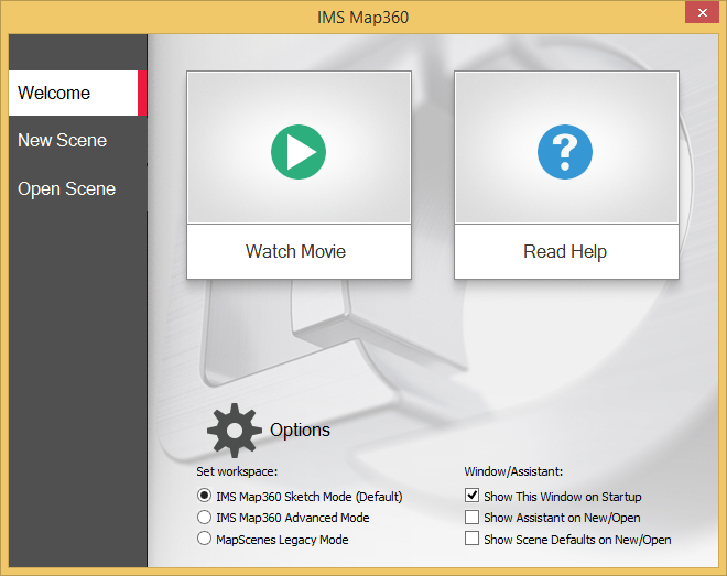
This is an opening dialog of IMS Map3600. The above dialog allows you to either Start a new scene or Open an existing scene, by selecting the appropriate option. You can also view an introductory movie or review the help files. Use the check boxes to set the options you would like to apply whenever you run the software. To begin this tutorial in "Sketch mode" please check on "IMS Sketch Mode" and pick "New Scene."
The above dialog allows you to either Start a new scene or Open an existing scene, by selecting the appropriate option. You can also view an introductory movie or review the help files. Use the check boxes to set the options you would like to apply whenever you run the software. To begin this tutorial in "Sketch mode" please check on "IMS Sketch Mode" and pick "New Scene." Configure the dialog as shown above.
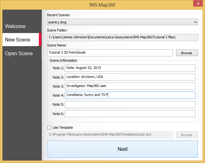
Scene Defaults
Next, switch to your "Home" Ribbon and select "Scene Defaults:" Configure as shown:
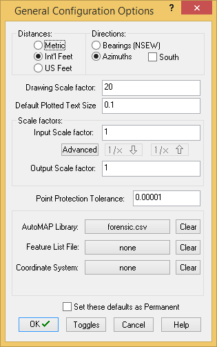
In this example, set the Distances= Int'l Feet, Directions= Azimuths, Drawing Scale Factor= 20, and Default Plotted Text Size (inch)= 0.1 Check on "Set these defaults as Permanent" if these are the units you normally work with and you will be able to skip this step in the future.
Note: The Drawing Scale Factor of 20 represents a drawing scale of 1 inch on the printed page equals 20 feet on the ground at the scene. It is often described as 1"=20'. In order to get this precise scaling it is necessary to enter a similar number in the printing dialog, which will be demonstrated later.
Additional Information:
- The International Foot is defined as exactly 0.3048 meters, while the US Survey Foot is defined as exactly 1200/3937 meters, so the difference between them is 2 parts per million (304,800 meters = 1,000,000 International Feet = 999,998 US Survey Feet). Generally speaking, US Survey Feet are only used in IMS Map360 when using GNSS to collect data.
- Azimuths are directions that are measured in a full 360 degree circle with North as the “zero” direction. The increasing angle is always clockwise.
- Bearings are defined as North, South, East or West. Directions are measured from North or South. For example: bearings are normally referenced as N 42° 16’ 23” W – this would mean 42 degrees to the left of north (towards the west).
- Angles are measured by instruments in degrees, minutes and seconds.
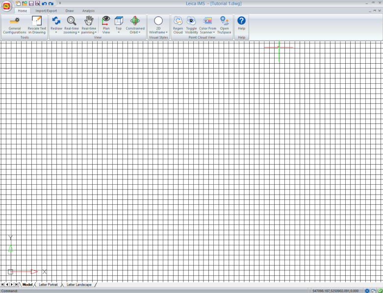
The Drawing Screen
You will then see the empty Drawing screen. Your system will show a black background, but we are using white in this guide because it prints better in a manual. We are now ready to start working.
Save
Pick the "Save" button to save your work:

If you would like to see an overview of how to import a pointcloud file that you did not process in Cyclone (see this article for an overview of currently supported formats) please review Part 2a.
Part 2a: See how you would import a PointCloud into Cyclone to create a database >
Otherwise skip directly to Part 2b so you can follow this tutorial using this provided sample data.