Options
Main Menu | Settings | Options
The options screen helps you set settings that affect the look and feel of FieldGenius.
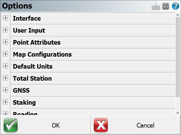
Press the [+] buttons along the left to expand (show) each section, and the [-] buttons to collapse (hide) it.
- Interface Options
- User Input Options
- Point Attributes Options
- Map Configurations Options
- Default Units Options
- Total Station Options
- GNSS Options
- Staking Options
- Roading Options
- System Options
Interface Options
Map Colour
Use this to force the background color for the main drawing area to be white or black
Map Orientation
Using this will force the map screen to be oriented to the north or south. This is needed for coordinate systems that are referenced south, such as in South Africa. This is different from South Azimuth directions, as used in Hawaii.
Arc Resolution
This option determines the number of segments that will displayed in an arc on the screen. Reducing this number increases program speed; increasing this number slows down graphics display, but improves the quality of arcs and curvy lines displayed on the screen.
Text Size (Info/Grid)
Use this to force the text shown in the Information screens (such as the Observation toolbar and the COGO History screen) and grid screens (such as the Project Manager and Angle Offset shots) to use a small or large sized text.
Show Scale Bar
Use this to turn the scale bar shown on the main map screen on or off.
Scrollbar Width
Use this to increase the width of the scroll bar on the map screen.
User Input Options
Keypad Text Color
Use this to turn change the keypad text color to show up better against the keypad background color.
Keypad Background Color
Use this to turn change the keypad background color so the text shows up better.
Extended Edit Boxes
Use this to control how you want to bring up the selected keypad when tapping in an edit box: either with a single tap, a double tap, or off. Users of devices with a keyboard should leave this set to Double Click, and users of devices without a keyboard should set this to Single Click. Setting this to Off disables both the keypad and any other commands that may be started directly from the edit field, such as the Point Chooser or Inverse Tool, so that edit fields can only be used for typing values from your physical keypad.
Menu Shortcuts
This will enable menu shortcuts so if you have a keyboard device you can press letter and number keys to navigate around the program.
Instrument Toolbar
You can define if the instrument toolbar is located on either the Right or Left Side of your map screen.
SIP Type
Use this to specify which SIP keypad type you want to use on a Windows Mobile device.
Point Attributes Options
Coordinate Order
Use this to control the display of coordinate values in FieldGenius. Options are NEH, ENH, XYZ, XYZ (South) and YXZ (South) affecting any area of the program where coordinates are displayed.
This option also affects whether the ASCII Import and ASCII Export commands use a N,E or E,N (X,Y) file format.
Alphanumeric IDs
When this is enabled you will be allowed to enter Alphanumeric Point IDs such as 21a, AB3, EV2. If this isn't turned on, then FieldGenius will not accept anything but integer numbers. Alphanumeric input of Point IDs can contain up to 31 characters.
Alphanumeric Case Sensitive
When this is enabled the Point ID that is used as a unique identifier will be case sensitive, points a1 and A1 will be recorded as 2 separate points.
Notes:
The Case Sensitive setting is applied when the user stores a measured, calculated, or manually entered point and FieldGenius needs to determine if the Point ID already exists. In other cases the setting is not used, specifically:
- Importing Points: When importing points the setting will not be applied. FieldGenius will treat the Point IDs as Case Sensitive, regardless of what the setting is.
- Point Ranges: Point ranges will be handled as Not Case Sensitive.
- Sorting Points: The Point Database and other sorting applications will always sort as Not Case Sensitive.
- Point Query: Specifying a Point ID as input will always require an exact match and is Case Sensitive.
Point ID Range - Minimum
Use this to force FieldGenius to limit the point numbers that are used to a specific range; here you would specify the minimum range value. If you try to use a point number that is less than this value, you will see a message that will ask you to select a different point number. Note: If you have the Alphanumeric IDs toggle turned on, a natural order sort algorithm determines if a Point ID falls within the range.
Point ID Range - Maximum
Use this to force FieldGenius to limit the point numbers that are used to a specific range; here you would specify the maximum range value. If you try to use a point number that is greater than this value, you will see a message that will ask you to select a different point number. Note: If you have the Alphanumeric IDs toggle turned on, a natural order sort algorithm determines if a Point ID falls within the range.
Alphanumeric Point ID's can have a maximum length of 31 characters.
Point ID Intervals
Enter the value that the next point will automatically increment by. The default is 1 and consecutive points will be recorded as 1,2,3 ... If the Point ID interval is set to 2 consecutive points will be recorded as 1,3,5,7...
LandXML Export - Prefix IDs
When this is enabled, point numbers will be prefixed with the point's description upon creation of an XML file. For example, if a point has a number of 100 and description of PIN, in the XML file its ID will be PIN100.
New Description Prompt
This controls how FieldGenius deals with descriptions that don't match anything in your AutoMap library. If this is on, when you enter a description that isn't in the AutoMap library you will see a warning message asking you if you want to add it.
If it is off, any description that doesn't have a match in the AutoMap library will be automatically added to your Project's AutoMap library.
Time Stamp Saved Points
This tells FieldGenius to write a timestamp into the raw file whenever a point is stored.
Write Notes to Raw File
When this option is enabled, the text note recorded for a specific point will be written to the Raw file as a comment.
Map Configurations
Show ID
This is used to show or hide the point number labels for your points.
Show Description
This is used to show or hide the point description labels for your points.
Show Elevation
This is used to show or hide the point elevation labels for your points.
Level of Detail
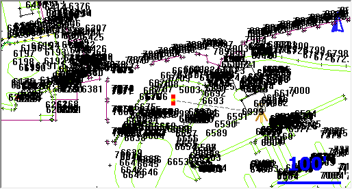
The Level of Detail filter, when turned off, will force FieldGenius to show the point labels all the time, independent of your zoom level. If it is turned on, FieldGenius uses an algorithm to determine if displaying the point labels is necessary.
This is demonstrated in the following two images, the first has LOD turned on and the second has LOD turned off.
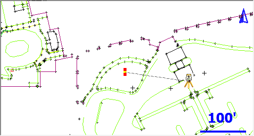
With LOD on, as soon as you zoom in to a reasonable level, the labels will appear automatically. Under normal circumstances you will keep the LOD feature active.
Text Size (Map View)
Use this to change the default text size that is used on the Map View.
Map Position Select
If this is turned on, tapping a blank part of the map screen will display the Map Select Toolbar.
Map Point Select
If this is turned on, then tapping on a point from the map screen will select the point tapped and show it as a blue circle and open the Point Toolbar. The point can then be saved as a recorded point in your Project.
Map Line Select
If this is turned on, then tapping on a line from the map screen will select it and open the Line Toolbar.
Map DXF Entity Select
If this is turned on, then tapping on a DXF entity will highlight it. If turned off then the DXF file will behave like an underlay and is not selectable.
Default Units Options
These options provide the default settings shown in the Units & Scale screen when creating a new Project; they do not necessarily reflect the actual settings for the current Project. Please see the Units & Scale topic for more detailed information on each option.
Distance Unit, Format, Precision
Specify whether new Projects should default to Meters or Feet, in which format, and with how much precision.
Angle Unit, Format, Precision
Specify whether new Projects should default to Degrees, Radians, or Gons/Grads, in which format, and with how much precision.
Direction Format
Specify whether to use Bearings or Azimuths by default for new Projects.
Scale
Specify the default ground-to-grid scale factor to use for new Projects.
Corrections
Specify whether to enable or disable the "Curvature and Refraction Corrections" option by default for new Projects.
Total Station Options
Default Measure Mode
This specifies which Measure Mode FieldGenius will default to, either Sideshot or Sideshot (Auto).
Quick Measure Modes
When this is turned on, when you press the Measure button in routines such as the Horizontal Angle Offset or Resections screens, it will force the instrument to take a measurement instantly. If this is turned off, then pressing the Measure button will take you back to the map screen where you have to press the measure button on the instrument toolbar to take a measurement.
If you're using a robotic instrument you will probably want to keep this turned off.
Traverse Reciprocate
When this is turned on, you will be able to use the Reciprocate Traverse option on the Backsight Summary screen, when occupying a traversed point. This recalculates your setup point's position, based on an average of the traverse shot to the point being occupied and the backsight shot from the point being occupied. If this is turned off, then the Reciprocate Traverse option within the Occupy Point routine will be grayed out. For additional details, please refer to the Backsight Summary topic.
Display Use Last Setup Screen
When this option is turned on, you will be offered to the choice to use the last instrument occupied point when for an existing Project is opened. This is useful if the program is inadvertently closed in the middle of a Project and the instrument has not moved from the last occupied point. You can start work again without having to backsight and reestablish the instrument location.
Use Assistant on Open
The Total Station Assistant suggests workflow shortcuts when opening a Project.
GNSS Options
EP+ Records
Toggle the format of the EP record written to the raw file. The standard EP record contains a combined horizontal RMS value, while the EP+ record contains RMS values for Northing and Easting. EP+ records are required when seeding positions with regards to L-band correction services.
Post Processing Tagging
Start and End times of GNSS measurements can be written to the raw file as comments. These values are required for post processing raw data with Effigis OnPOZ (EZSurv) software. NOTE: End times are captured when the user picks the Store Position button on the GNSS Measurement dialog.
Leap Seconds (GPS-UTC)
Some receivers report UTC time instead of GPS time. When writing Start and End times for GNSS measurements, the Leap Seconds value will be applied to the UTC time to ensure GPS time is recorded. NOTE: This value will change over time and is the responsibility of the user to ensure it is current. This value only applies to those receivers that report UTC time.
Prompt Raw Logging
Raw data logging on most receivers must be manually initialized. A prompt can be displayed at connection time to remind the user to start raw data logging on the receiver.
Test Incoming Data Stream
Some GNSS receivers automatically connect to the previous correction link. FieldGenius can test for incoming corrections at connection time to eliminate the Link Configure step.
Display GNSS Reference Setup
When connecting to a reference receiver, a prompt can be displayed to remind the user of the steps to take to complete a reference setup.
Staking Options
Note: You can also access these options directly from the staking toolbar.
Tolerance
This is the error tolerance that the staking command will use. When your staking "move by" distances are equal to or less than this amount, your direction to a point will be indicated in green text in the Observation Toolbar at the top left hand corner of the screen. Green text will be displayed to notify you that you're meeting your tolerance; if you do not meet the tolerance, the text will switch to red.
Orientation Total Station
The user can set an orientation preference for a Total Station layout. Depending on the equipment currently in use, FieldGenius will automatically use the defined orientation.
Orientation North (Cardinal)
With the North orientation, North is the reference direction. The "move by" distances are standard cardinal directions.
North: This is the distance you need to move North.
South: This is the distance you need to move South.
East: This is the distance you need to move East.
West: This is the distance you need to move West.
Cut: This is the amount you have to go down from the current rod position to the stake point's elevation.
Fill: This is the amount you have to go up from the current rod position to the stake point's elevation.
Orientation North (Directional)
With the North orientation, North is the reference direction. The "move by" distances are indicated by arows showing the direction of the movement.
Up arrow: This is the distance you need to move North.
Down arrow: This is the distance you need to move South.
Right Arrow: This is the distance you need to move East.
Left Arrow: This is the distance you need to move West.
Cut: This is the amount you have to go down from the current rod position to the stake point's elevation.
Fill: This is the amount you have to go up from the current rod position to the stake point's elevation.
Instrument
With the staking reference set to Instrument the map view will be twisted so the instrument is centered towards the top of your screen. The "move by" distances are with respect to the rod position looking towards the instrument. This view is useful when using a robotic instrument.
In: This is the distance you need to move towards the instrument.
Out: This is the distance you need to move away from the instrument.
Right: Facing the instrument, move right by this amount.
Left: Facing the instrument, move left by this amount.
Cut: This is the amount you have to go down from the current rod position to the stake point's elevation.
Fill: This is the amount you have to go up from the current rod position to the stake point's elevation.
Prism
With the staking reference set to Prism the map view will be twisted so the prism is centered towards the top of your screen. The "move by" distances are with respect to the instrument man looking at the prism. This view is handy when using a non-robotic instrument.
In: This is the distance you need to move towards the instrument.
Out: This is the distance you need to move away from the instrument.
Right: Facing the prism, move right by this amount.
Left: Facing the prism, move left by this amount.
Cut: This is the amount you have to go down from the current rod position to the stake point's elevation.
Fill: This is the amount you have to go up from the current rod position to the stake point's elevation.
User Point
With the User Point orientation, you can use an existing point in your Project as the reference. The view will be twisted so that the selected point is centered towards the top of your screen.
In: This is the distance you need to move towards your user reference point.
Out: This is the distance you need to move away from your user reference point.
Right: Facing your user reference point, move right by this amount.
Left: Facing your user reference point, move left by this amount.
Cut: This is the amount you have to go down from the current rod position to the stake point's elevation.
Fill: This is the amount you have to go up from the current rod position to the stake point's elevation.
Line
With the staking reference set to Line the map view will be twisted so the line is drawn vertically with the start of the line at the bottom of the screen and the end of the line at the top of the screen. The "move by" distances are with respect to the line.
In: You will not be given an In distance.
Out: You will not be given an Out distance.
Right: Looking down the line (or parallel to it), move right by this amount perpendicularly towards the line.
Left: Looking down the line (or parallel to it), move left by this amount perpendicularly towards the line.
Cut: This is the amount you have to go down from the current rod position to the stake line's interpolated elevation.
Fill: This is the amount you have to go up from the current rod position to the stake line's interpolated elevation.
Orientation GNSS
The user can set an orientation preference for a GNSS layout. Depending on the equipment currently in use, FieldGenius will automatically use the defined orientation.
Orientation North (Cardinal)
With the North orientation, North is the reference direction. The "move by" distances are standard cardinal directions.
North: This is the distance you need to move North.
South: This is the distance you need to move South.
East: This is the distance you need to move East.
West: This is the distance you need to move West.
Cut: This is the amount you have to go down from the current rod position to the stake point's elevation.
Fill: This is the amount you have to go up from the current rod position to the stake point's elevation.
Orientation North (Directional)
With the North orientation, North is the reference direction. The "move by" distances are indicated by arows showing the direction of the movement.
Up arrow: This is the distance you need to move North.
Down arrow: This is the distance you need to move South.
Right Arrow: This is the distance you need to move East.
Left Arrow: This is the distance you need to move West.
Cut: This is the amount you have to go down from the current rod position to the stake point's elevation.
Fill: This is the amount you have to go up from the current rod position to the stake point's elevation.
User Point
With the User Point orientation, you can use an existing point in your Project as the reference. The view will be twisted so that the selected point is centered towards the top of your screen.
In: This is the distance you need to move towards your user reference point.
Out: This is the distance you need to move away from your user reference point.
Right: Facing your user reference point, move right by this amount.
Left: Facing your user reference point, move left by this amount.
Cut: This is the amount you have to go down from the current rod position to the stake point's elevation.
Fill: This is the amount you have to go up from the current rod position to the stake point's elevation.
User Line
TBD"
Line
With the staking reference set to Line the map view will be twisted so the line is drawn vertically with the start of the line at the bottom of the screen and the end of the line at the top of the screen. The "move by" distances are with respect to the line.
In: You will not be given an In distance.
Out: You will not be given an Out distance.
Right: Looking down the line (or parallel to it), move right by this amount perpendicularly towards the line.
Left: Looking down the line (or parallel to it), move left by this amount perpendicularly towards the line.
Cut: This is the amount you have to go down from the current rod position to the stake line's interpolated elevation.
Fill: This is the amount you have to go up from the current rod position to the stake line's interpolated elevation.
Compass Switch Threshold
This allows a user to input a distance within which the compass on a Total Station.
Staked point ID Method
Use this drop down list to select the mode you want to use to number new staked points.
None: This options does not change the point ID number when a staked point is saved (e.g. the Point ID 5 is staked then the Staked point ID will be 5, since this point exists you will need to manually rename the staked Point ID).
Next: This increments the staked point ID number to the next available point number in the sequence (e.g. if you stake Point ID 5 and the last stored point on the project is 60 the Staked Point ID will be 61).
Additive: This adds a number defined in the Additive Number field to the Point ID number being staked (e.g additive number is 1000 and the Point ID is 5 the Staked Point ID will be 1005).
Prefix: This adds a Prefix number or letter defined in the Prefix value field to the Point ID number being staked. (e.g. Prefix value is set to S and the Point ID number is 5 the Staked Point ID will be S5).
Suffix: This adds a Suffix number or letter defined in the Suffix value field to the Point ID number being staked. (e.g. Suffix value is set to S and the Point ID number is 5 the Staked Point ID will be 5S).
Additive Number
The number entered into this field will be added to the Point ID number being staked to generate a Staked Point ID number.
Prefix Value
The number or letter entered into this field will be added before to the Point ID number being staked to generate a Staked Point ID number.
Suffix Value
The number or letter entered into this field will be added after to the Point ID number being staked to generate a Staked Point ID number.
Line Mode
Use this to control how your navigation distances are computed and displayed when staking a Line.
In Auto mode, FieldGenius will automatically determine if it should display in/out or left/right offsets to the line. Auto mode will display in/out distances if the line of sight intersects the line equal or greater than 45° (In/Out); if it is less than 45° then FieldGenius will display (Left/Right) offsets to the line.
You can force FieldGenius to always display In/Out distances to the line by setting it to In/Out.
Use Left/Right to always see the Left/Right offset to the line.
If you're staking an arc, FieldGenius will always display in/out offsets no matter what line mode setting FieldGenius is set to.
This option has no effect if you have selected the "Line" Orientation Reference option.
Robotic Prism Tracking
When selected the robotic total station will track the prism as the user moves it across the scene site.
Turn Instrument Mode
If you have a motorized instrument, including robotics, you can control how FieldGenius turns the instrument during stakeouts. If you want FieldGenius to compute the horizontal and vertical angle needed to stake your point, use the 3D (HA + VA) option. If all you want is the horizontal angle to be turned, and the vertical left alone, select the 2D (HA) option.
Cut and Fill Slopes
Use this to specify your cut and fill slopes when you’re slope staking. The fill slope value will be used when the hinge point is higher than the calculated catch point and this will occur in areas that require a fill. The cut slope will be used when the hinge point falls below the calculated catch point. This will occur in areas that require a cut.
A Cut of 2:1 means you would have a cut of 1 unit for every 2 units traveled horizontally.
DTM Staking Name
Use this to select a surface that will be used to compute a new z value for the design point. When you select a surface you need to have the Stake to DTM toggle checked. Once this is turned on, the elevation for any point you stake will be computed using this surface. In other words, if you’re doing point staking and the point has a design elevation, it will be ignored. The stake point’s N & E will be used to intersect a point on the surface and that elevation will be used to stake the point.
Fade Staked-Out Points
Place a check mark in this box if you would like to see
Display Point Staking Screen
Place a check mark in this box if you would like to see the Point
Display Stake Result Screen
Place a check mark in this box if you would like to see the
Store Stake Point
Place a check mark in this box if you would like the
By default this is checked. What will happen is when you store a staked position using the store button on the stake toolbar you will be prompted with a screen allowing you to assign a point number and description to the new point that will be created.
The point description will default to the current description from the AutoMap Library, as shown on your topo toolbar. If you choose a different description from the library, then it will be retained for all consecutive stakeout points.
Furthermore, when this feature is turned on it will use the value in the Add Id field to determine the point number for the recorded staked position. For example if you staked point 19 and you have an Attached User Id = 1000, then FieldGenius will automatically use 1019 as a point number. This can be changed by the user.
Show Staked-Stored Points
Place a check mark in this box if you would like to see the
Use Stake List
Place a check mark in this box if you would to use the
Find Next Nearest
Place a check mark in this box if you would like
Roading Options
Stationing Format
You can specify the format for your stations.
|
Value |
Stationing Format |
||
|
0+000.000 |
0+00.00 |
0.000 |
|
|
10 |
0+010.000 |
0+10.00 |
10.000 |
|
100 |
0+100.000 |
1+00.00 |
100.000 |
|
1000 |
1+000.000 |
10+00.00 |
1000.000 |
|
10000 |
10+000.000 |
100+00.00 |
10000.000 |
Force Tangential
Place a check mark in this box if you would like to automatically enforce the direction of alignment geometry elements so they remain tangential to previous geometry elements. This rule can be useful to ensure the alignment geometry elements maintain a common tangent direction between adjacent elements.
Dynamic Horizontal Alignment
Place a check mark in this box if you would like changes to the direction of alignment geometry elements to be applied to subsequent geometry elements. To illustrate: modify the direction of a line geometry element by 10° clockwise. With this feature is enabled, all geometry elements following the modified line will also be rotated by 10° clockwise. With this feature is disabled, only the single line element will be rotated by 10°.
System Options
Show Tool Tips
When turned on, a "Tip of the Day" will be displayed when FieldGenius is started, and tooltips will be displayed when you hover over any button.
Turning this off will hide the "Tip of the Day" dialog and will disable tooltips on buttons.
Communication Trace File
When turned on it will create a log file of the communication between FieldGenius and your instrument, which can be used to diagnose communication problems and should only be used in this situation. The text file will be named TraceTS.txt or TraceGNSS.txt and will be created in the ...\Program Files (x86)\MicroSurvey\FieldGenius\12\ directory on your device.
Always Auto-Reconnect
When turned on it the program will always attempt to reconnect if communication drops between the device and the collector.
Datum Warning Dialog
When turned on a warning will show up when the datum is changed so the user can move to use a new datum.