MultiSet
Main Menu or Instrument Toolbar | Measure Modes | Multi-Set
The Multiset routines in FieldGenius allows you to record angular sets in any order you want. You can also review your measurement's computed average and standard deviation.
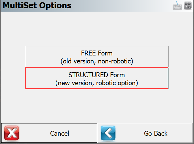
There are (2) two MultiSet work-flows to choose from, (1) MultiSet - Free Form and (2) MultiSet - Structured. The MultiSet - Free Form supports manual measurements. The MultiSet - Structured option is intended to take advantage of robotic total station ability to turn and take measurements automatically. Select the appropriate method from the MultiSet Options Screen
Starting the MultiSet - Free Form Routine
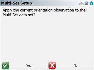
If you've previously measured to your backsight and are confident that it hasn't changed very much you can save some time by using the "Apply the current orientation observation to the Multi-Set data set?" option. If you select Yes, it will take the last backsight measurement you made and use it for the multiset session.
You will then see the Setup Occupy Point screen. If you've already established a setup, it will display the same information that you previously entered.
Press the Continue Multi-Set button to proceed to the Multi-Set Point List screen
Note:
Unlike the regular setup routine, you will not be required to immediately shoot your backsight.
Multi-Set Point List
This is the control center for recording your sets. It will begin with a record for your backsight and your foresight measurements will be listed after it, in order that they are measured.
Pnt: This is the point number of the point you've measured for your backsight and foresight points. If you see the word "Bearing" this indicates that you assumed a backsight direction.
Type: This is the type of measurement that was measured. It will be either a BS (backsight) or FS (foresight) measurement.
Obs F1:This will list the total Face 1 (Direct) observations that were recorded for the point.
Obs F2: This will list the total Face 2 (Reverse) observations that were recorded for the point.
Saved: If the foresight measurement hasn't been saved you will see a red "X". measurements that have been saved will have a green "checkmark". Since your backsight readings are always to a known point or an assumed direction you will see N/A as there is nothing to save.
Measuring the Backsight
If you want to shoot your backsight, then do the following.
-
Select the first row which is the backsight record by tapping on it.
-
Press the Measure button to start the measurement process.
-
On the map screen confirm that you have selected the correct target height.
-
When you're ready to record the measurement press the Measure button on the instrument toolbar.
-
You will automatically see the multiset point list where you will see your measurement which will be indicated in the F1 or F2 field.
Reviewing the Backsight measurements
If you press the Edit Set button you will see a summary of the two measurements.
The summary will display the standard deviations for the averaged measurements as well as the computed average measurement. In the list you will see the delta difference between the measured measurement and the average. In our example the HA and VA on the face 1 measurement was larger than the average direction by 11 seconds.
By default all measurements will be used to compute the averaged position. However, you can decide what measurements you want to use to compute the averaged position by pressing the green checkmark icon. Doing so will switch it to a red "X" which will remove it from the computation.
Notes about measuring the Backsight:
When you first begin the multi-set routine, you are not required to shoot the backsight prior to measuring a foresight.
You are not required to have both a Face 1 and Face 2 reading recorded for the backsight. A measurement on either face will work, but it is common practice to record both.
Measuring a Foresight
To record a foresight measurement you first have to define a point number in the Point ID field towards the top of the multi-set point list. Press the Next button to display the next available point ID, or type in the Point ID you want to use. Then press the Add button to add the new Point ID into the Multi-Set Point List. After you add the new point number follow these steps to record the measurement.
-
Press the Measure button to start the measurement process.
-
On the map screen confirm that you have selected the correct target height.
-
When you're ready to record the measurement press the Measure button on the instrument toolbar.
-
You will automatically see the multiset point list where you will see your measurement to your foresight points. They will have the FS tag in the Type column.
Reviewing Foresight measurements
To review you foresight measurement for any point, simply highlight it in the list and press the Edit Set button.
Towards the top you will see the foresight point you measurement to and a summary of the total face 1 and face 2 measurements recorded.
Next you will see the standard deviation that is computed using all the directions that have a green check mark.
Next is the averaged direction (plate reading) to the foresight point.
Finally, you will see the computed clockwise angle between the average backsight and foresight direction.
By default all measurements will be used to compute the averaged position. However, you can decide what measurements you want to use to compute the averaged position by pressing the green checkmark icon. Doing so will switch it to a red "X" which will remove it from the computation.
Once you're satisfied with your observations you can press the Store Pnt button which will take you to the Store and Edit screen. From here you can review the description and store it as either a SS or TR measurement.
Note: After you store your point, you will not be able to add anymore observations.
Auto Turn Sets
If you have a motorized instrument you will be able to have FieldGenius plunge your scope and turn back to the foresight or backsight for you.
Simply highlight the measurement you want to record an observation for, and select the Auto Turn option so the checkbox is checked.
Now when you press the Measure button the instrument will automatically plunge and turn back to your foresight point for you. You can then press the measure button on the instrument toolbar to record the measurement.
When you're using the Auto Turn option FieldGenius will first check to see how many Face 1 and Face 2 observations you have. It will automatically keep these numbers equal to one another. For example if you have 1 Face1 measurement, and 2 Face2 measurements, FieldGenius will automatically sight the foresight using Face 1.
Furthermore, if you're instrument is equipped with auto target recognition, you can use this feature in combination with the auto turn for greater productivity.
Multiset Measure Modes
At any time during the collection of your observations you can choose to shoot an angle & distance or angles only measurement. You can control this by pressing the Measure Modes button on the instrument toolbar.
If you're measuring to a foresight you need a minimum of 1 distance before you will be allowed to store it.
Raw File Record
When you store your multi-set points a point is created in the database as well as some records in the raw file.
--MultiSet (StdDev HA:0°00'03" VA:0°00'04" SD:0.005m)
OC,OP1,N 1000.0000,E 1000.0000,EL100.0000,--
SP,PN5,N 1015.5153,E 1000.0000,EL99.1936,--BS
BK,OP1,BP5,BS0.00000,BC359.59495
RB,OP1,BP5,AR0.00000,ZE93.42400,SD15.5479,HR5.000,--BS
RB,OP1,BP5,AR179.59390,ZE266.17420,SD15.5512,HR5.000,--BS
RF,OP1,FP8,AR45.52150,ZE92.03370,SD22.3917,HR5.000,--FS
RF,OP1,FP8,AR225.52100,ZE267.56580,SD22.4311,HR5.000,--FS
RF,OP1,FP8,AR225.52100,ZE267.57000,SD22.4311,HR5.000,--FS
RF,OP1,FP8,AR45.52180,ZE92.03350,SD22.3917,HR5.000,--FS
SS,OP1,FP8,AR45.52132,ZE92.03185,SD22.4114,--FS
For each foresight point you store; a OC record is created to indicate the setup information. Also a BK record will be written to record which point you specified for the backsight. An important thing to note here is that the BC value will be equal to the average backsight direction (plate reading) recorded for the backsight.
The Standard Deviations are written into the first comment record, and it will also display "Tolerance Exceeded" if applicable.
RB records are your accepted measurements to the backsight.
RF records are your accepted measurements to the foresight.
The last item will always be a SS or TR record. This is the averaged direction (plate reading) to the foresight point.
Starting the MultiSet - Structured Routine
MultiSet Settings
In the MutliSet - Structured work-flow the settings screen allows you to configure the MultiSet.
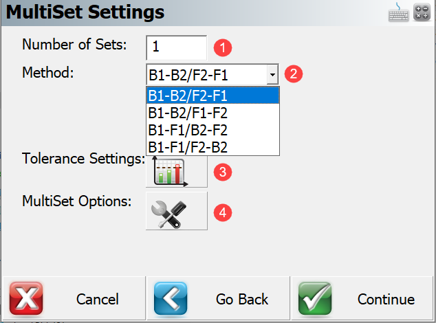
1. Number of Sets This input box allows user to define the number of sets that are to be collected to each point. The set is defined as a direct (Face 1) and reverse (Face 2) reading to the backsight and the foresight.
2. MethodThis drop list allows user to specify the data collection observation order. User can select from 4 following options.
| Method | Observation Order (3 Points) | |
|---|---|---|
| 1 | B1-B2/F2-F1 |
Backsight – Face1, Backsight – Face2, Foresight A – Face 2, Foresight A – Face 1, Foresight B – Face 1, Foresight B – Face 2 |
| 2 | B1-B2/F1-F2 |
Backsight – Face1, Backsight – Face2, Foresight A – Face 1, Foresight A – Face 2, Foresight B – Face 1, Foresight B – Face 2 |
| 3 | B1-F1/B2-F2 |
Backsight – Face 1, Foresight A – Face 1, Foresight B – Face 1, Backsight – Face 2, Foresight A – Face 2, Foresight B – Face 2 |
| 4 | B1-F1/F2-B2 |
Backsight – Face 1, Foresight A – Face 1, Foresight B – Face 1, Foresight B – Face 2, Foresight A – Face 2, Backsight – Face 2 |
3. Tolerance SettingsThis button opens a screen where a user defines the tolerance settings of repetitive data observations.
Horizontal Angle Tolerance (sec) - Use this to specify the tolerance for the averaged (Face 1, Face 2) observations of the horizontal angles in seconds.
Vertical Angle Tolerance (sec) ' Use this to specify the tolerance for the averaged (Face 1, Face 2) observations of the vertical angles in seconds.
Distance Tolerance - Use this to specify the tolerance for the averaged (Face 1, Face 2) observations of slope distance in meters.
If any of the standard deviations (std. dev. of HA, VA or distance) of the measured points exceeds the set tolerance value, you will be notified while storing the point.
4. MultiSet Options This button opens a screen where the user controls automatic aiming to the targets (robotic instruments only).
- Auto Turn – This toggle allows the user to control robotic movement of the instrument.
- Auto Read – This toggle allows the user to control if the measurement will be triggered automatically (for prisms only - using ATR (Automatic Target Recognition)).
Backsight Setup
Backsight set up is required before any data collection method can be selected by the user. The backsight point defines the plate reading and orientation of the instrument. Backsight orientation is used to determine the desired direction if foresight points are already known. The backsight reading is the first reading of every set.
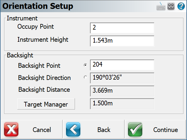
Cancel – Will exit the Multiset- Structured function.
Back - Will go back to the Multiset – Structured Settings.
Continue – Will go to the measure screen to take the backsight observation.
Add Foresight Point to the Point List
When the backsight set up (Face 1) measurement is completed the BS record is added to the point list.
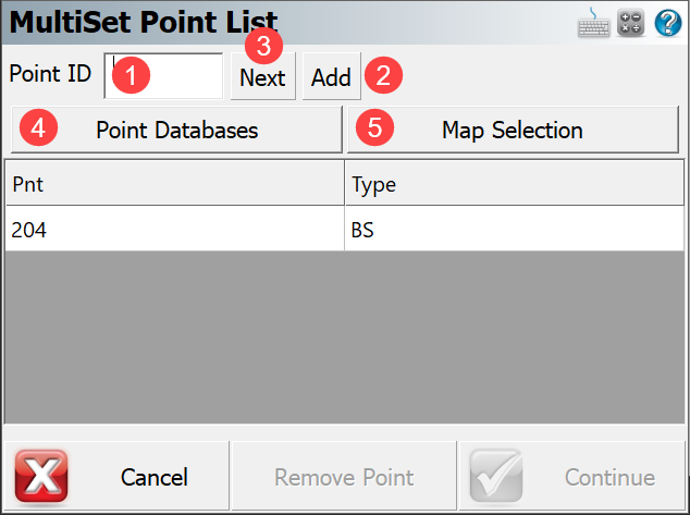
1. Number of Sets To continue with the Multiset function a minimum of one foresight point is required. To add new (unknown) foresight points to the point list the user can, (1) enter a point ID in the input box, (2) select Add button or (3) use Next button which gives the user the next available ID from the point database. To add a point which already exist in current job (known point) the user has the option to (4) select a desired point(s) from the database or (5) from the map.
Cancel – Will exit the Multiset- Structured feature.
Remove point - Will remove the highlighted point from the point list (point # 3 in the example).
Continue – Will go to the measure screen to take following observation from the selected sequence.
Collect Data in Selected Sequence
User must complete the first measurements to each target point. The procedure is the same for all data collection observation order methods. Using the fist two methods (B1-B2/F2-F1, B1-B2/F1-F2) the user will trigger a measurement to the first point and the observation in the opposite face will be taken automatically. Using the third and forth method (B1-F1/B2-F2, B1-F1/F2-B2) observations to each target point must be completed in the first face initially. When this is done the second face measurement to each target point is completed automatically. When the user starts to take mutliset measurements the Multiset Observation screen is displayed. The elements of the Muliset Observation screen are described below.
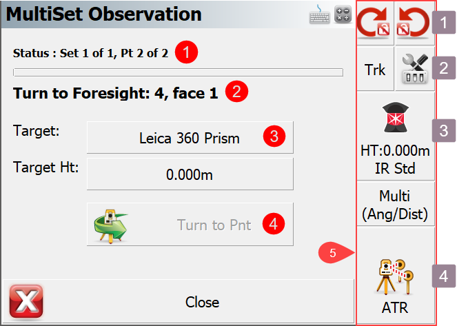 1. Status Status row shows how many sets will be collected and how many points are in the point list
2. Point Instructions The second row tells user what target point and what face of total station telescope should be observed next.
3. Target Type & Target Height These buttons open the Target manager and show the status of the selected target.
4. Turn to Point Button This button will become active if the robotic function has been disabled in Multiset Options screen.
1. Total Station Toolbar This tool bar allows the user to, (4) take a measurement, (1) control power search, (2) turn laser on/off, turn ATR on/off, check level bubble, (3) access target manager and much more.
Review and Manage Data
Multiset Data review screen show user to how many sets of observations have been collected and whether they comply with the user defined tolerance levels. The elements on the Multiset Data Review screen are described below.
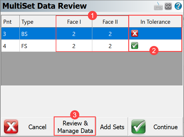
1. Face Measurements Displays the number of face measurements taken of each point. number of measurements taken for each face related to a point ID
2. In Tolerance Displays the number of face measurements taken of each point.
3. Review & Manage Data This buttons opens the Multiset Observation screen with more detailed information on the point measurements.
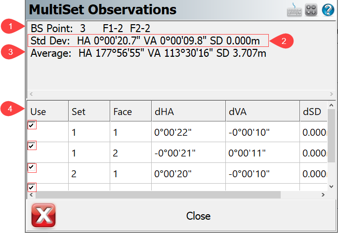
The elements on the MultiSet observation screen are.
1. Status Observations The first row shows point number and how many observations in face 1 and face 2 have been used for the calculation of average direction to backsight value.
2. Standard DeviationsThe second row displays the standard deviation of horizontal angle, zenith angle and slope distance. The standard deviations are compare to the user defined tolerance settings.
3. Average Angle and DistanceThe third row displays the averaged horizontal angle, zenith angle and slope distance.
4. Select ButtonA user has an option to control whether observation will be used in calculation or not by checking (default) or unchecking the selection box.
Store Point
The store point screen allows you to review the point information, change the point ID and store the MultiSet point.
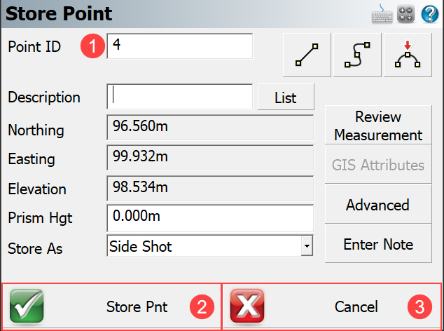
1. Point ID Click this field to edit and change the default Point ID to add a prefix, suffix or change the point number to any points ID which does not already exists in the point database.
2. Store PointThis button will store the point to the database, if a point already exists the Existing Point ID dialog will appear.
3. Cancel This button will not save the Point ID to the database. However, the RAW observations made during the multiset will be saved in the raw file. Averaged values (of HA, VA and SD) used for the calculation of a foresight point are saved in the raw file as a commented line.
Example: --SS,OP1,FP4,AR180.44498,ZE113.06281,SD3.7560,--
If the user defined tolerance is exceeded a warning screen will appear before the point is stored. The YES button takes the user back to the storing point screen and allows them to store the point even though it is out of tolerance. . The NO button takes the user
back to the view and manage data screen. The user may collect more data or exclude some data to potentially have the observations within the set tolerance criteria.
Note: All records are recorded and an accidentally cancelled records can be restored by editing the RAW file.
RAW File
The list of records that are written to the RAW file when using the MultiSet - Structured feature are listed and described below.
Raw file
1 --MultiSet (Tolerance settings HA:0°00'05" VA:0°00'05" SD:0.001m)
2 --Sequence: B1-F1/F2-B2
3 --Point # 5: (StdDev HA:0°00'09" Tolerance Exceeded VA:0°00'08" Tolerance Exceeded SD:0.000m)
4 LS,HI0.000,HR0.000
5 OC,OP1,N 100.0000,E 100.0000,EL100.0000,--
6 --setup_time,DT09-25-2018,TM16:07:37
7 BK,OP1,BP3,BS177.57174,BC177.56542
8 BR,OP1,BP3,AR177.56542,ZE113.31430,SD3.7035
9 RB,OP1,BP3,AR177.57174,ZE113.31322,SD3.7037,HR0.000,--
10 RB,OP1,BP3,AR357.56311,ZE246.28062,SD3.7033,HR0.000,--
11 RF,OP1,FP5,AR181.07211,ZE113.05065,SD3.7399,HR0.000,--
12 RF,OP1,FP5,AR1.07032,ZE246.54381,SD3.7396,HR0.000,--
13 SS,OP1,FP5,AR181.07121,ZE113.05142,SD3.7397,--
Description
Row 1 - Which multiset feature has been selected for data collection and required tolerance settings
Row 2 - Sequence in which the data has been collected.
Row 3 - Foresight point with standard deviations of observed values and warning text “Tolerance Exceeded”
if applicable.
Row 4 - LS (Line of Sight Record), HI (Height of instrument), HR (Height of rod).
Row 5 - OC (Occupy Point Record), OP (Point number), N (Northing), E (Easting), EL (Elevation),
-- (Description).
Row 6 - Time when FS point was observed.
Row 7 - BK (Backsight Record), OP (Occupy point), BP (Back point), BS (Backsight), BC (Back circle).
Row 8 - BR averaged values from accepted observations of Horizontal Angle, Zenith Angle and slope distance.
AR (Angle Right), ZE (Zenith angle), SD (Slope distance)
An important thing to note here is that the BC value (Row 7) will be equal to the average backsight
plate reading recorded for the backsight.
Row 9 & 10 - RB records (Repeat Backsight) are user’s accepted measurements to the backsight
AR (Angle Right), ZE (Zenith angle), SD (Slope distance), HR (Height of rod)
Row 11 & 12 - RF records (Repeat Foresight) are user’s accepted measurements to the foresight
AR (Angle Right), ZE (Zenith angle), SD (Slope distance), HR (Height of rod)
Row 13 - SS record (Side shot) this is the averaged observation values to the foresight point.
AR (Angle Right), ZE (Zenith angle), SD (Slope distance)