Alignment Staking - Part 1
There are two things that have to happen before you can stake a road.
- You have to create an alignment, vertical profile and a template. Or…
- Import a LandXML file and use XML cross sections to stake from.
Stake from Alignment, Profile and Template.
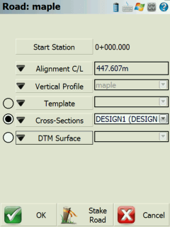
If you've taken the time to define your alignment, you need to select the vertical profile and template that you want to stake from in the road settings screen.

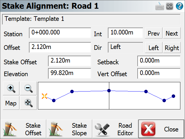
Use the Stake Road button to start the road staking which will display the Stake Alignment screen.
Station and Station Interval
If you enter a station interval, it will move forward and back along the alignment by this amount when you use the Prev and Next buttons. This interval will start from the station that is currently entered in the Stake Station field.
Stake Station
You can also manually enter the station you would like to stake by entering it in the Station field.
Design Offsets
Move Along Template
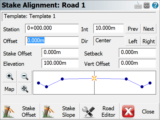
You can move along the template by using the Left and Right buttons. As you do this the offset from the centerline will be displayed in the Offset field. Furthermore you will see what side of the template you're on by looking at the direction field. You will also note in the template preview, the "x" visually marks the design offset.
Define an Offset
You can define your own offset to stake by entering the value in the Offset field. To enter a Left offset, use a negative value.

Stake Offset and Setback
Stake Offset
By default the Stake Offset will equal the Offset value. The stake offset is designed to help you enter the offset that you want to stake your point at. Sometimes, the contractor asks you to stake a point at a certain distance from the centerline, this will help you do that.
Setback
The setback and stake offset fields work in conjunction with one another. You will note that as you enter a stake offset, a value is computed in the setback field. This value is computed by subtracting the Stake Offset from the Design Offset.
If you know that the offset or setback for a template point is to be a specific value, enter the value in the setback field; the stake offset field will update automatically.
You will note that when a setback or stake offset is defined, you will see an orange circle in the preview screen. This circle indicates the location of the setback.
Note: If you want to make sure that you're staking nothing but design points along the template, then make sure the Setback field is equal to 0.0.
Elevation and Vertical Offset
Elevation
The field will show you the computed elevation on the template at the design offset specified. This value can be changed to allow you stake a different elevation.
Vertical Offset
This field works in conjunction with the elevation field. If the user enters a different elevation than the one that was computed on the template, the difference between the elevations is shown in the vertical offset field.
If you know what the vertical offset is for the point you're staking on the template, you can enter it in this field. You will see the elevation for the point update to reflect the offset you defined.
In the template preview screen you will see an orange circle. This circle indicates the location of the vertical offset point that will be staked.
Note: If you want to make sure that you're staking nothing but design points along the template, then make sure the Setback field is equal to 0.0.
Template Preview
You can zoom into your template using the zoom controls. You can also pan the template by tapping on it and dragging it on the screen.
Use the Map button to display the location of the template along you alignment. This will be displayed in the map view window.
Stake Offset
Once you've defined that point you want to stake, you can select the Stake Offset button to start the staking process. When you press this button you will see the staking toolbar. For an explanation of the staking toolbar and alignment staking, please refer to the next section, Alignment Staking - Part 2.
Stake Slope
This is the Stake Slope toggle. Normally you will slope stake from the hinge point on the template, but it is totally up to you. The slope staking feature can be used from any point on the template.
Road Settings
Press this button to return to the road settings screen.
Stake from LandXML Cross Sections
To stake cross sections from a LandXML file you first need to import it using the LandXML importer found in the Import Menu.
You can then select the alignment form the map screen to open the Roads Manager, or you can access it form the Roads Menu. In this menu you can select the alignment that has the cross sections, and then press the Road Settings button.
You then have to select the cross section that you want to use by selecting it in the cross sections field.
When you press the Stake Road button you will see the Stake Alignment screen which is described in detail above.
Stake Alignment with a Reference Line
To stake to an Alignment using a Reference Line the user needs to first import in a XML file containing an alignment then a DXF file is needed for the Reference Line information. Use the Importer feature found in the main menu to bring in both data files.
After this is completed go into the Roads Manager to select which road alignment to use. Continue by pressing the Manage Road button to take you to the Road Settings page. The Alignment info should be updated and reflect a valid Start Station and Alignment C/L length. From here the user must define a line by pressing the Select Reference Line button at the bottom of the list of settings.
By pressing this it will take the user to the Map View where you can navigate around the screen to select the appropriate DXF linework to be used in as the Reference Line in the routine. Once selected press the OK button to take you back to the Road Settings page where the label for that line will now be displayed.
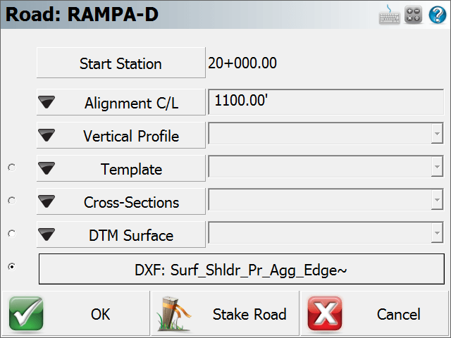
Press the Stake Road button if you are satisfied with the selected road alignment and reference line to proceed to the Stake Reference Line setup page.
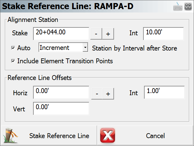
From the Stake Reference Line dialog the user can customize the features work flow by the following settings;
Alignment Station
In this section the user has the ability to set which Station location to start at and the interval distance to use when proceeding to the next station. There are additional settings to further control the moving from one station to another.
The AUTO check box when check ON will automatically move up the next station interval by either incremental or decremental along the alignment after a point has been stored.
The Include Element Transition Points check box when checked ON will stop at the next vertical and horizontal deflection point along the alignment. This will ignore the station interval value to ensure a key transition point is not skipped over.
Reference Line Offsets
Here the user can enter in a Horizontal and Vertical offset value. This offset will be calculated from the point on the referenced line. An interval can also be applied here manually for the horizontal offset value.
When you are satisfied with the values entered press the Stake Reference Line button to continue to the Stake Point screen. After a point has been successfully staked out and stored the routine will go back to the Stake Reference Line window. Alternatively pressing the Cancel if you wish to back out to the Map View screen.