Bolt Patterns
Main Menu | Survey Tools | Bolt Pattern
This routine allows you to create or edit point patterns, and apply them to existing points in your project. This is useful for creating drill holes for bolt patterns, pillar columns, etc.
Note
The *.pattern data files are completely interchangeable between both FieldGenius and MicroSurvey CAD or inCAD, so any patterns created in one program can be edited or used in the other.
Pattern Toolbar
When you start the Point Pattern command, you will see the Pattern Toolbar along the bottom of your map screen.
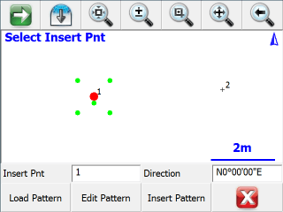
Insert Pnt
Specify the point ID for an existing point in your project, either by typing in its point ID, or by tapping on a point in the map screen to select it when this field has focus.
The selected point will be highlighted in the map view with a large red point, and the current pattern will be previewed with smaller green points.
Direction
Use this to specify a direction value for your pattern. The default direction of N0°00'00"E will orient the pattern exactly as it was defined.
To orient your pattern along any arbitrary line between two existing points, enter those two points using the pt#..pt# format like 1..2 and the direction between those two points will be automatically calculated for you. The pattern's X-axis will be applied along this direction.
Load Pattern
Press this button to load a previously saved *.pattern file.
Edit Pattern
Press this button to edit the currently loaded pattern, or to create a new pattern if you have not loaded one. Please see below for more information on the Pattern Editor.
Insert Pattern
Press this button to apply the currently pattern to the selected insertion point. New points will be stored in your project at the coordinates, as previewed by the green pattern points. All inserted points will be created with the description "Pattern", and with the same elevation as the selected insertion point.
To insert a pattern onto multiple points, simply change the insertion point and insert the pattern onto each point one-at-a-time as desired.
Pattern Editor
When you press Edit Pattern on the Pattern Toolbar, you will see the Pattern Editor screen.
Enter the X and Y offset values for your pattern as desired. As you enter the points, they will be previewed in the grid, which will automatically zoom to the extents of your pattern. Please see the Distance Entry & Recall topic for options on entering the offset values in various units.
The 0,0 origin will always be located at the selected Insertion Point, so a point should not be included in your pattern at 0,0. You can also rotate the pattern into any orientation on the Pattern Toolbar (see above), so you do not need to create different variations of the same pattern to insert it in different orientations.
Press the Delete Point button to remove the selected X,Y offset from the pattern.
Load Pattern
Press this button to load a previously saved *.pattern file.
Save Pattern
Press this button to save the current pattern to disk.
This will always do a "Save As" type save, so you can specify a new filename, or select any existing pattern file to overwrite it with the changes. You will always be prompted for confirmation before overwriting an existing pattern file.
New Pattern
To create a new pattern, simply delete all of the existing points from the current pattern. When you press the Save Pattern button you will always be prompted for a new filename, so you will not lose the previous pattern.
Close
Press this button to close the Pattern Editor and return to the Pattern Toolbar. If you have not saved the current pattern, you will be prompted to confirm this before discarding your changes.