Vertical Plane Projection
Main Menu or Instrument Toolbar | Measure Modes | Intersections | Vertical Plane Projection
This function is for locating multiple points on a vertical place defined by two previously measured points. The program will calculate the distance for each shot taken to an un-measurable position so that coordinates can be generated for the shot.
An example of how you could use this would be to shoot two corners of a wall to define a vertical plane. Then you could sight four corners for window on the second floor and FieldGenius will use the HA and VA values and compute the intersection with the vertical plane. Once the intersection is computed, the point will be stored.
Function
When the command is started you will see a screen that will allow you to specify the points that will form the baseline for the vertical plane.
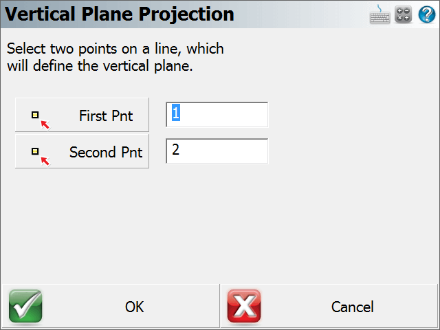
Note: You need to measure and store the points that will be used to define the vertical mapping plane, prior to starting the Vertical Projection command.
When ready to continue, press the OK button.
You will now be in the Vertical projection mode which will be indicated by the Measure Mode button on the instrument toolbar. To begin calculating points on the vertical plane, you need to point the total station at the new point you want to create. To complete the shot, press the measure button, and then store the point.
Note: You do not need to use a prism when measuring points on the vertical plane. Simply point the instrument at the point you want to create.
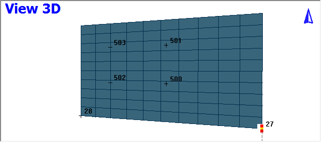
Since vertical planes represent 3D data, it is sometimes necessary to rotate your perspective of the Project to help you see the point you're computing on the vertical plane.
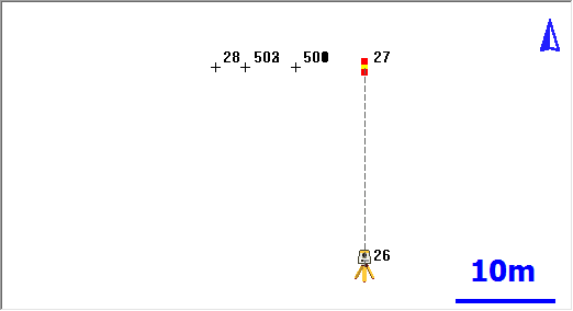
Press the 3D View button on the display toolbar which will open the 3D toolbar. If you press the Planar View button, your scene will be rotated so it matches your perspective. For example, a vertical plane was defined by points 27 and 28. When the planar view option is used, you can see your work in a 3D perspective. You can now see the 4 measurements (points 500 – 503) that were made to record the position of a window on the vertical plane.
|
|
| Plan View | 3D Perspective |
You can also hide objects that are behind the vertical plane from viewing by pressing the Vert Grid button. In the example below, you will see that after this is turned on, some of the line work is hidden from view.

To exit this routine, simply switch to a different Measure Mode.
Raw File
Each point that is computed on the vertical plane will also have a computed sideshot stored in the raw file.
--VS,PA27,PB28
SS,OP1,FP503,AR142.24510,ZE78.37170,SD17.8888,--VERTICAL
For each shot you record you will see a note before the shot in the raw file indicating which points were used to define the vertical plane.
Special Notes
Vertical projection measurements will automatically be recognized by your MicroSurvey CAD or inCAD desktop software. Please refer to the MicroSurvey CAD or inCAD help file for more information regarding importing vertical projections.