Manual Entry - Alignment C/L
Main Menu | Roads Manager | Edit Road | Alignment C/L
To define the centerline data press the Alignment C/L button which will open a menu. On this menu select Edit to open the C/L Editor.
If you're entering a new road the C/L Editor will not have any elements listed. In the example shown below there are three elements defined; 2 tangents and 1 curve element. In the element list, it will always display the length of the element and its end station. Furthermore, all elements that are defined will be displayed in the Map so you can visually confirm that the geometry is correct.
Delete C/L Alignment
You cannot delete a C/L Alignment once it has been created.
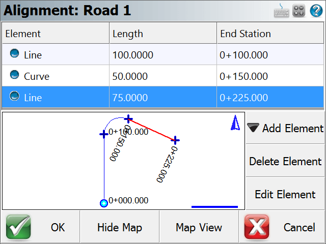
The C/L Editor can display a view of the map along the bottom. This view can be toggled on and off by pressing the Show Map/Hide Map button.
If you would like to zoom into or pan around the map, press the Map View button which will display zoom and pan controls. Press the Close View button when you want to return the C/L Editor.
Adding an Element
To add an element to a road you need to use the Add Element button. Once you press this you will see 5 options appear that will help you define the different elements supported by FieldGenius.
- Line (Tangent)
- Curve
- Spiral
- Spiral-Curve-Spiral
- Chain
Tip: When you're prompted for a distance or direction, you can always use the distance and direction recall features just like you would for COGO calculations.
Line (Tangent) Element
In the Line Element editor, gray fields indicate fields that cannot be edited. All other non gray fields can be edited by the user. When you enter your known values and have confirmed their correctness, press OK to save these values, or press Cancel to exit without saving.
A tangent is defined by a direction and length. There are four ways you can define the tangent and they are explained in further detail below.
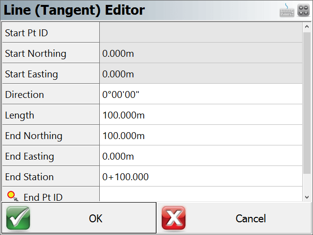
Direction and Length
If you know these two values, you can enter them in their respective fields. You will see that the end coordinates and end station will be computed automatically.
End Nothing and End Easting
If you know the coordinates for the end of the tangent, you can enter them in the End Northing and End Easting fields. Once you've done this, the direction, length and end station fields will be updated automatically.
Direction and End Station
If you know the direction and end station of the tangent, enter these known values in their respective fields. Once you've done this, the length and end coordinate fields will be updated automatically.
End Point ID
If you have a point in the project database that defines the end of the tangent, you can enter the point number in the ID field, or use the point chooser to select it from the map. Once you've done this, the direction, length, end coordinates and end station fields will automatically be updated.
Curve Element
When you select this option your will see the curve editor with most of the fields being empty.
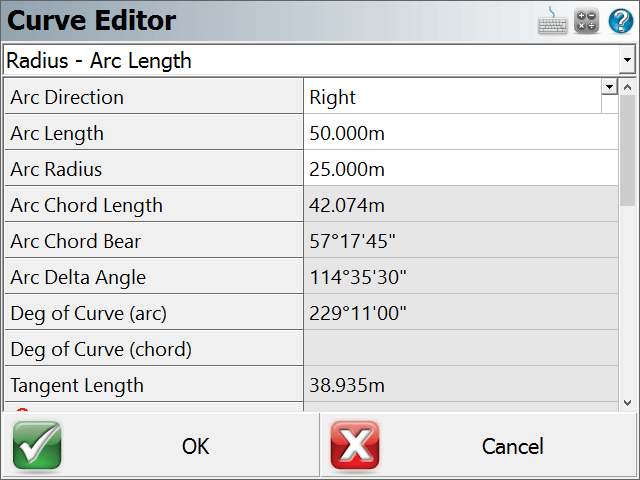
Define Known Data
You first have to define what known information you want to use to compute the curve. If you click on the drop down list you will see a list of all the options that can be used to compute the unknown values.
Enter the Known Data
Once you define the known data format, you will see grayed out fields which indicate they can't be edited. White areas indicate fields that can be edited, and these fields will match what you defined in the first step.
- You always have to define the direction for the curve, either right or left.
- Enter your know values.
- You don't have to specify the PC point, the function will assume that you're beginning at the end of the last leg.
- A PC Tangent direction will automatically be computed based on the previous tangent. You can always over ride this value if you need to define a non-tangent curve.
- Press OK to save your inputted values, Cancel to exit without saving.
Spiral Element
When you select this option your will see the spiral editor. This will help you define a spiral segment for your alignment.
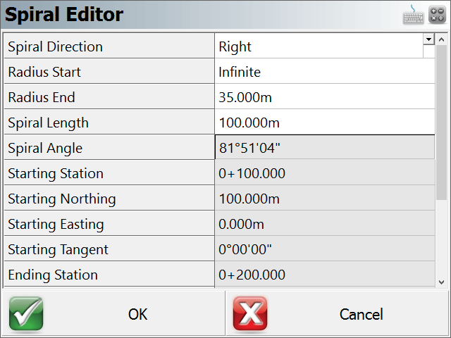
Define Known Data
To solve for this type of element you need to know:
- Spiral Direction
- End Radius
- Spiral Length
In the editor, gray fields indicate fields that cannot be edited. All other non gray fields can be edited by the user.
Press OK to save your inputted values, Cancel to exit without saving.
Spiral – Curve – Spiral

Define Known Data
To solve for this type of element you need to know:
- Spiral Direction
- Spiral In Length
- Spiral Out Length
- Curve Radius
- Curve Length
In the editor, gray fields indicate fields that cannot be edited. All other non gray fields can be edited by the user.
Press OK to save your inputted values, Cancel to exit without saving.
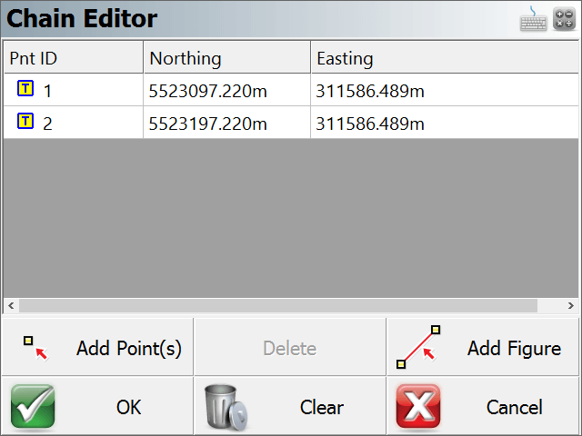
Chain
Use this option if you want to select points or figures in your drawing to define the centerline and the profile (optional).
When you select the Add Figure option you will be taken to the map screen where you can select a figure.
You can also add points individually by using the Add Points(s) button.
Press OK to save the chain, press Cancel to exit without saving.
Note:
You should only select Tangent sections for a Chain. If you Add a Figure which contains arcs or splines, the chain will straight-line any curved segments, so the resulting Chain length and stationing will not be the same as the original Figure.
Chain Element
When you return to the road editor you will see that a chain element has been created. Chain elements differ from regular elements in that even though a chain can be made up of line and curve elements, it will appear in the list as a chain.
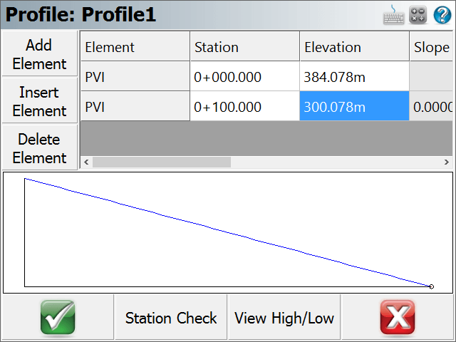
Auto Profile
After you press OK, you will be asked if you would like to create a vertical profile based on the chain point's elevation. If you select Yes, then you will be prompted for a Profile Name.
Vertical Profile
As mentioned above, a vertical profile can optionally be created automatically. If this option is chosen by the user, PVI points will be created for the profile. Each PVI point represents the points that make up the chain.